About
necAnalyzer is an online NEC infrared remote control decoding and analysis tool. It analyzes the received level data to perform basic infrared decoding and graphically display the infrared level signals. It also compares the data with the NEC protocol standard definition to assist in analyzing the quality of infrared remote control signals.
How to use the tool:
- On the tool page, click the floating icon in the lower left corner, enter the formatted data, and click "Decode" to analyze the data.
- Data terminal, used to receive infrared signals and format the output data. a) You can manually copy the data to the tool through debug output; b) You can also automatically upload and parse the data through USB/network.
- Server side: Only required when the terminal uses the network (e.g., WIFI), see subsequent sections for details.
Data Format
1. Each data bit is enclosed in curly braces
-
The first position represents the level: 0 or 1
-
The second position represents the duration of the level in microseconds (us)
2. The standard 0038 reception header defaults to a high level output, and outputs a low level when a signal is received. The NEC protocol start bit is 9ms, so the standard start bit should be: {0:9000}
3. Data explanation
- The valid data should consist of a 2-bit preamble + 16-bit user code + 16-bit user code inverse + 16-bit command code + 16-bit command code inverse, totaling 66 bits.
- It is recommended to add {0:562}{1:0} at the end of the data to indicate the end of the data, totaling 68 bits.
PS.
- Content outside the curly braces will be automatically filtered out.
- The default data filled on the web page comes from the ESP-IDF example routine: ir_nec_transceiver.
Automatic Parsing
Data can be automatically uploaded and parsed via USB or network. If you're up for it, you can totally use both at the same time!
USB Upload
Connect the device to your computer, click "Connect Device," and select the appropriate port.
* If the device is not found, it is recommended to check the device manager to ensure the drivers are installed correctly. Common USB to serial converter drivers include: CH340/CH341, CP210x.
Network Upload
The solution is based on WebSocket implementation. Due to server latency and bandwidth limitations, you currently need to set up your own server:
Server Side
- Download the server and unzip it to a path that does not contain Chinese characters.
- Run start.bat in the server's root directory or execute node ws.js in the console.
* Requires a Node.js environment, tested version v20.15.1.
Web Client
- After the server is running, a console window will pop up where you can view device connection status. Closing this window will stop the service process.
- If the server and the web page are on the same device, use the default address 127.0.0.1. Otherwise, enter the local network address as prompted in the server window.
- Ensure that the terminal and the server are on the same local network.
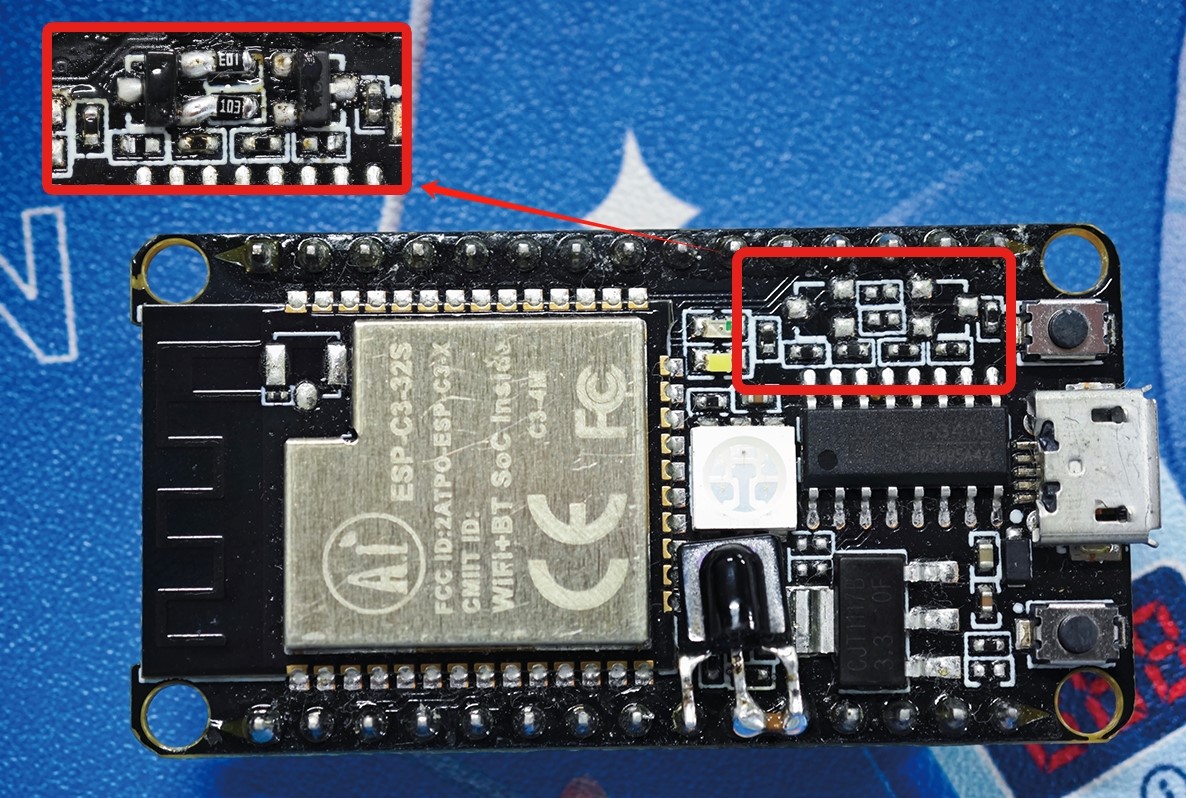
Terminal Devices
USB-Serial Communication
- ESP32 Firmware: nec_analyzer_uart_esp32_Firmware
PIN_UART_TXD = 1, PIN_UART_RXD = 3, PIN_IR = 23 - ESP32-C3 Firmware: nec_analyzer_uart_esp32_c3_Firmware
PIN_UART_TXD = 21, PIN_UART_RXD = 20, PIN_IR = 8 - IDF Source Code: nec_analyzer_uart_Source
- * When using the CH34X USB to serial chip, be sure to use a dual-rail automatic download circuit to prevent communication abnormalities. For details, see Hello AI-Thinker

WiFi-webSocket Communication
- IDF Source Code: nec_analyzer_webSocket_Source
- Not sure how to configure the server address and port during network setup, forget it, just hard-code them, it's not like it's unusable.jpg, maybe update it someday.
Flashing
You can use the Flash Download Tool or ESP Launchpad for flashing.
Interface Documentation
Serial Communication
- Send the formatted data via serial port
- After sending the valid data, send an empty message to indicate the end: \r\n
Network Communication
- Forward the data received from the terminal device to the web client in string format via the websocket service
- The server identifies the client and terminal device through the protocol field
The client is identified as necAnalyzerClient, and the terminal device is identified as
necAnalyzer.
You can customize the connection identifier for the terminal device on the server side.
NEC Protocol
There are already numerous explanations about the NEC protocol online, so I won't repeat them here. No "official documentation" was found, but you can refer to SB-Projects - IR - NEC Protocol for more information.
An interesting point is that in the Extended NEC protocol found in the materials, the user code inverse is also included in the user code, expanding the user code from 8 bits to 16 bits. The instruction data segment is still parsed using 8 bits + inverse checksum, while the IDF example routine parses the data code as 16 bits.
I don't get it, I really don't. I found out about the SB-Projects website through their example routines!
To prevent misunderstandings among beginners, the display of the 16-bit code
will temporarily follow the ESP-IDF example routine, but...
Surprise, I didn't plan on parsing the extended protocol, so if the inverse checksum doesn't
pass, the parsing result will not be displayed and a prompt will be given, but the logic
waveform will be shown. You're on your own with that.